
Godot will tell you almost anything about a mesh. How many surfaces it has, where every vertex is, what the UV map looks like, the whole inventory. There is exactly one question it shrugs at:
Given a texel in my texture, which bit of the surface is that?
Sounds useless. It is not useless. It is the question hiding underneath every effect where a mark has to land where you put it and then STAY there. Damage that piles up on an enemy exactly where you shot it. Scorch marks. Mud. Rust. Wear.
So we are going to build the thing that answers it: a CPU triangle rasterizer, about 140 lines, that walks every triangle in a mesh and writes down where every single texel lives in 3D.
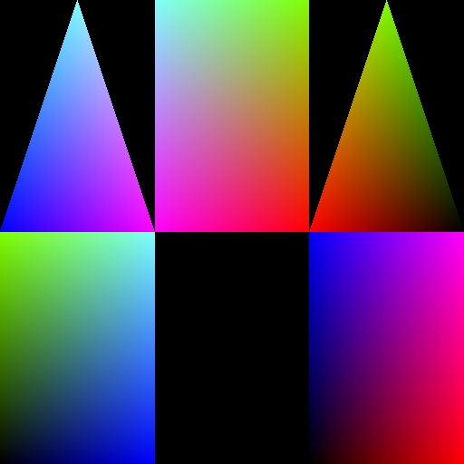
A baked position map of Godot's built-in PrismMesh. RGB is the object-space XYZ of the surface point that lands on each texel.
That is the output. A rainbow smear in the shape of your UV islands, and the least impressive-looking useful texture you will ever generate. It is a texture that knows where it is.
This is simple stuff for a seasoned veteran of graphics programming, an abstruse mess for a beginner. So, I'll try to go slow. I'll also be using Godot's functions to abstract away the data collection part. We don't need to know how a mesh's vertices are stored, we just need to use them.
The plan
A rasterizer sounds terrifying and then turns out to be three things stapled together:
- A box. For each triangle, the rectangle of texels it could possibly touch.
- A test. For each texel in the box, is it inside the triangle or not?
- A blend. For each texel that survives, mix the three corners' values.
That's it. That's the whole program. Every section below is one of those three, and two of them share a single function.
We start with a mesh and a target resolution, and we come out the other side with two textures. A position map, where each texel holds the object-space XYZ of the surface point that maps to it, and a normal map holding that point's normal. That second one is not the normal map you are probably thinking of. This normal map has nothing to do with faking surface detail. It is the normal of the individual texel, in object space. Just hang in there.
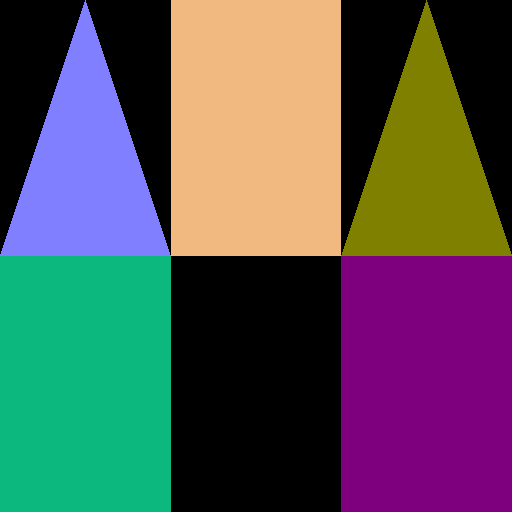
The normal map from the same bake, same islands, same layout. RGB is the object-space normal, remapped from -1..1 into 0..1 so it survives a PNG.
Put those two next to each other and they tell you something for free. Position always changes as you move across a face, so a position map is gradients all the way down. A normal only changes if the mesh says it does, so this one is five flat blocks of colour: one per face, five faces, hard edges between them. Which is correct for a prism.
Bake a character and look at the same pair. If the normal map is gradients where you expected flat panels, your normals got smoothed on import, and you have just found that out by looking at a picture instead of by wondering why your lighting is soft.
public static Maps Bake(Mesh mesh, int resolution)
{
    var pos = Image.CreateEmpty(resolution, resolution, false, Image.Format.Rgbah);
    var nrm = Image.CreateEmpty(resolution, resolution, false, Image.Format.Rgbah);
    pos.Fill(new Color(0, 0, 0, 0));
    nrm.Fill(new Color(0, 0, 0, 0));

    ...

}
Well, this is easy. Godot gives us the Image resource, so we just create two of them.
Two things in there look boring and are not. Rgbah is half-float, not the Rgba8 your fingers want to type.
Object-space positions are signed and happily larger than 1, and 8 bits cannot hold that at all. Half float can.
Take the memory hit.
And Fill sets the alpha (that 4th parameter) to 0. Pay attention to that. It will matter later. I will
remind you.
Collecting the mesh surfaces
Now we need to write to those images, which means we need to figure out what to iterate. Thankfully Godot makes
it easy for us. We'll be using three things, all on the Mesh resource:
GetSurfaceCount(): gives us the number of surfaces on the meshSurfaceGetArrays(surfaceIndex): gives us an array of everything that makes up a surfaceMesh.ArrayType: a utility enum that maps to what is being held at what index of the array the method above returns
Scary stuff, especially the last two. So here is a smaller snippet before we dive into the real thing:
Vector3[] verts = mesh.SurfaceGetArrays(surfaceIndex)[(int)Mesh.ArrayType.Vertex].AsVector3Array();
Still scary. Let me go word by word.
mesh.SurfaceGetArrays(surfaceIndex): returns a bunch of arrays in an array.(int)Mesh.ArrayType.Vertex: this is a number. It is also the index of the surface arrays we want to use to get the vertex. That's what this enum is for.- Both of these combined give us a
Godot.Collections.Array. Not very useful on the C# side. - So we add
.AsVector3Array()to the end to make it aVector3[]of the vertices of that surface.
That's it. Now we do the same for the other things we need, UV and normals:
Godot.Collections.Array arrays = mesh.SurfaceGetArrays(surfaceIndex);
Vector3[] verts = arrays[(int)Mesh.ArrayType.Vertex].AsVector3Array();
Vector2[] uvs   = arrays[(int)Mesh.ArrayType.TexUV].AsVector2Array();
Vector3[] norms = arrays[(int)Mesh.ArrayType.Normal].AsVector3Array();
And then we wrap the whole thing in that GetSurfaceCount() function:
for (int s = 0; s < mesh.GetSurfaceCount(); s++)
{
    Godot.Collections.Array arrays = mesh.SurfaceGetArrays(s);
    Vector3[] verts = arrays[(int)Mesh.ArrayType.Vertex].AsVector3Array();
    Vector2[] uvs   = arrays[(int)Mesh.ArrayType.TexUV].AsVector2Array();
    Vector3[] norms = arrays[(int)Mesh.ArrayType.Normal].AsVector3Array();

    ... magic will happen here ...

}
And that's how we collect the raw data we need for our wild and wicked use case.
Finding the triangles
Now we need to process our data. We need to iterate over the triangles but... we have no triangles right now, just a bunch of arrays.
Well, the triangles are hiding in plain sight. Here, I'll show you.
int[] idx = arrays[(int)Mesh.ArrayType.Index].AsInt32Array();
This ugly thing has everything we need. It is THE INDEX BUFFER.
Only thing you need to know about the index buffer is that it is magic, and it holds indices for other arrays in
groups of three. verts, uvs and norms are parallel per-vertex arrays: index i gives you vertex i's
position, uv, and normal. idx is a list of numbers that index into those, three at a time, each triplet naming
one triangle.
Which means the array is shaped like this:
  idx = [ 0,1,2,  0,2,3,  ... ]
          └tri0┘  └tri1┘
Indexing exists so that shared vertices can be stored once. But the sharing rule is stricter than it looks. A vertex isn't just a position in space, it is a bundle of attributes: position, normal, uv, tangent, colour. Two triangles can share a vertex only if EVERY attribute agrees, not just the position. A cube corner sits at one place but carries three different normals depending on which face you arrived from, so it gets stored three times. That's why a cube is 24 verts and 36 indices instead of 36 duplicate verts.
So, knowing this fact, we can do this:
int triCount = idx.Length / 3;
We now know the triangle count on our surface! Huzzah, that was easy!
Oh, wait... what is that...
for (int t = 0; t < triCount; t++)
{
    int i0 = idx[t * 3];
    int i1 = idx[t * 3 + 1];
    int i2 = idx[t * 3 + 2];
    covered += RasterTri(pos, nrm, resolution,
        uvs[i0],   uvs[i1],   uvs[i2],
        verts[i0], verts[i1], verts[i2],
        norms[i0], norms[i1], norms[i2],
        ref bounds, ref boundsInit);
}
...This is how we iterate over the triangles
We iterate over the triangle groups. i0, i1, i2 are our indices that we'll be using in verts, uvs and
norms.
And now three variables show up that I have been keeping from you. covered, bounds and boundsInit, all
declared up next to the Fill calls. covered counts texels written. bounds grows to enclose everything we
wrote. boundsInit remembers whether bounds has been seeded yet. Keep them in mind. We'll cash all three in
later.
RasterTri is the next thing. Its signature looks like this:
int RasterTri(
    Image pos, Image nrm, int res,
    Vector2 uv0, Vector2 uv1, Vector2 uv2,
    Vector3 p0, Vector3 p1, Vector3 p2,
    Vector3 n0, Vector3 n1, Vector3 n2,
    ref Aabb bounds, ref bool boundsInit
)
What it does is barycentric-ly fill one triangle in 'UV-times-resolution' pixel space and return the number of texels written. A bit confusing, I know. It'll make sense in a minute.
Triangle rasterization (and why you are going to wish you never found those triangles)
In computer graphics, rasterisation or rasterization is the task of taking an image described in a vector graphics format and converting it into a raster image which represents the original image.
That is what Wikipedia says, and it confuses even me. So here is mine:
Rasterization is deciding which cells of a grid a shape covers, and what value each cell gets.
A triangle rasterizer is that, for triangles. It is essentially how computers draw and understand triangles.
And doing it yourself, in a loop you wrote, is what makes it a software rasterizer.
Nearly everything written about software rasterizers is aimed at a screen. If that's the one you want, with the incremental edge stepping and the subpixel precision and all the rest of it, go read 'the triangle rasterizer' by Kristoffer Dyrkorn and come back. We're going the other way. Same edge function, different destination, and the destination changes more than you would think.
Regardless. I'll do my best.
Texel coordinate space change
We are now inside RasterTri. First thing we do is move into texel space, pixel space, whatever you want to call
it.
Vector2 a = uv0 * res, b = uv1 * res, c = uv2 * res;
That's a coordinate space change. UV coordinates are normalized, so they live in a unit square. The image we are
painting into is not a unit square, it is res texels across. So we multiply the UV positions by our resolution
to get (a, b, c) points in texel space.
Written out:
  given that res is '512'

  uv (0.25, 0.25)  ->  a = (128, 128)
  uv (0.75, 0.25)  ->  b = (384, 128)
  uv (0.50, 0.75)  ->  c = (256, 384)
Simple enough. And from here on, "the screen" is the texture and "the pixels" are texels. Everything else you have ever read about rasterizers applies unchanged.
The Edge Function
A triangle has 3 edges... Shocking, I know.
We need to know where points fall relative to those edges. For that, we use the edge function:
private static float Edge(Vector2 p, Vector2 q, Vector2 r) =>
    (q.X - p.X) * (r.Y - p.Y) - (q.Y - p.Y) * (r.X - p.X);
You really, really, really, really don't need to understand how it does what it does. You need to understand what it does. Trust me on this.
This monstrous glob of math takes two points, p and q, draws a vector from p to q, then asks two
questions about r:
- Is
ron the correct side? For our case that's the right hand side of the p->q vector. ('Correct' is a complicated term here, I'll talk about it later.) - How far is
rfrom that p->q vector?
And it answers both at once, in one number:
- the sign (positive or negative) tells us if
ris on the correct side - the magnitude tells us the area of the triangle p, q, r. Twice the area, actually.
Go on, drag it around until both of those fall out:
Edge(p, q, r)
What it is
the 2D cross product of
u = q - p and v = r - p
= twice the signed area of
the triangle p, q, r
drag the dots, arrow keys nudge
Edge comes out positive. In texel space Y runs downward, so positive is the right-hand side of the arrow. Which side counts as positive never matters to the bake, only that the two sides disagree.Five subtractions, two multiplies, and that is the entire mathematical content of a triangle rasterizer. Everything else in this post is loops.
Three edges, three weights
Okay, whatever. Why do we need it then? Well, we need it for this:
float denom = Edge(a, b, c);
float inv   = 1f / denom;

float w0 = Edge(b, c, pt) * inv;
float w1 = Edge(c, a, pt) * inv;
float w2 = Edge(a, b, pt) * inv;
Run the same function three times, once per edge, always against the same point. Each answer is twice the area of
a smaller triangle: the one made by pt and the edge OPPOSITE one corner. Divide by twice the area of the whole
triangle and you get that corner's weight. The wedge opposite a vertex is that vertex's weight.
denom = Edge(a, b, c)
weights
interpolate
p = p0*w0 + p1*w1 + p2*w2
denom flips sign, every Edge flips sign, and the weights do not move. That is the whole reason the code divides before it tests. Drag the point outside and a weight goes negative, because the wedge it names has flipped over the far edge.Boom! Everything came together, celebration!
Three payoffs fell out of that figure and every one of them is load-bearing.
The signs are the inside test. Drag pt out over an edge and the wedge opposite the far corner flips over,
its area goes negative, and the weight goes with it. So "all three weights are non-negative" IS "the point is
inside the triangle", and we get it for free out of numbers we needed anyway.
The weights sum to exactly 1. The three wedges tile the whole triangle, so their areas add up to the whole
area, and dividing by denom normalizes that to 1. So w0 + w1 + w2 will always be equal to 1!
And here is what 'correct side' was hiding. Hit Swap b and c. Every Edge call flips sign. denom flips
sign with them. And the weights do not move, because a negative over a negative is the same positive. Which side
counts as 'correct' never mattered. Dividing by a SIGNED area cancels the winding order out of existence. Every
other rasterizer tutorial opens with "assume counter-clockwise winding" and then never mentions it again, like a
hostage situation. We just don't care.
Rasterize the world
Below is the entirety of the RasterTri function. Brace yourself.
...actually don't. You already know every line in it.
private static int RasterTri(Image pos, Image nrm, int res,
    Vector2 uv0, Vector2 uv1, Vector2 uv2,
    Vector3 p0, Vector3 p1, Vector3 p2,
    Vector3 n0, Vector3 n1, Vector3 n2,
    ref Aabb bounds, ref bool boundsInit)
{
    Vector2 a = uv0 * res, b = uv1 * res, c = uv2 * res;

    float denom = Edge(a, b, c);
    if (Mathf.Abs(denom) < 1e-6f) return 0; // degenerate UV triangle
    float inv = 1f / denom;

    int minX = Mathf.Clamp((int)Mathf.Floor(Mathf.Min(a.X, Mathf.Min(b.X, c.X))), 0, res - 1);
    int maxX = Mathf.Clamp((int)Mathf.Ceil (Mathf.Max(a.X, Mathf.Max(b.X, c.X))), 0, res - 1);
    int minY = Mathf.Clamp((int)Mathf.Floor(Mathf.Min(a.Y, Mathf.Min(b.Y, c.Y))), 0, res - 1);
    int maxY = Mathf.Clamp((int)Mathf.Ceil (Mathf.Max(a.Y, Mathf.Max(b.Y, c.Y))), 0, res - 1);

    int written = 0;
    for (int y = minY; y <= maxY; y++)
    for (int x = minX; x <= maxX; x++)
    {
        var pt = new Vector2(x + 0.5f, y + 0.5f);

        float w0 = Edge(b, c, pt) * inv;
        float w1 = Edge(c, a, pt) * inv;
        float w2 = Edge(a, b, pt) * inv;
        const float e = -1e-4f;
        if (w0 < e || w1 < e || w2 < e) continue;

        Vector3 p = p0 * w0 + p1 * w1 + p2 * w2;
        Vector3 n = n0 * w0 + n1 * w1 + n2 * w2;
        n = n.LengthSquared() > 1e-12f ? n.Normalized() : Vector3.Up;

        pos.SetPixel(x, y, new Color(p.X, p.Y, p.Z, 1f));
        nrm.SetPixel(x, y, new Color(n.X, n.Y, n.Z, 1f));

        bounds = boundsInit ? bounds.Expand(p) : new Aabb(p, Vector3.Zero);
        boundsInit = true;
        written++;
    }
    return written;
}
I'll go line by line.
float denom = Edge(a, b, c); the denominator. We use this to turn raw areas into barycentric weights. It scales everything, cancels the winding, hoists the division out of the
loop.
if (Mathf.Abs(denom) < 1e-6f) return 0; Sometimes triangles are lying to us. If all the UVs are lined up, it
is not a triangle, it is a degenerate triangle. So skip those. Real meshes are full of them, usually from an
unwrap that collapsed an edge, and dividing by their zero area would stuff infinities into your texture.
float inv = 1f / denom; utility variable to make our life easier.
This thing below is the scary bounds math:
int minX = Mathf.Clamp((int)Mathf.Floor(Mathf.Min(a.X, Mathf.Min(b.X, c.X))), 0, res - 1);
int maxX = Mathf.Clamp((int)Mathf.Ceil (Mathf.Max(a.X, Mathf.Max(b.X, c.X))), 0, res - 1);
int minY = Mathf.Clamp((int)Mathf.Floor(Mathf.Min(a.Y, Mathf.Min(b.Y, c.Y))), 0, res - 1);
int maxY = Mathf.Clamp((int)Mathf.Ceil (Mathf.Max(a.Y, Mathf.Max(b.Y, c.Y))), 0, res - 1);
A triangle has bounds, it can be enclosed in a rectangle. So we do that by finding the min and max x and y of the corners. It means we test twenty texels instead of all of them.
That Clamp is doing a second job, though, and it is not optimization. UVs are not required to sit inside 0..1. A
tiling unwrap deliberately runs outside, uv * res lands outside the image, and without the clamp that's an
out-of-bounds write.
for (int y = minY; y <= maxY; y++)
for (int x = minX; x <= maxX; x++)
{
    ...
}
Here, we walk the nested loop.
var pt = new Vector2(x + 0.5f, y + 0.5f);
This thing grabs the middle of the texel. x and y here are grid indices, pt is the actual point that gets
tested. So it needs to be at the center of the texel. This one half-texel offset has more consequences than
anything else in the function and it gets its own section at the end.
float w0 = Edge(b, c, pt) * inv;
float w1 = Edge(c, a, pt) * inv;
float w2 = Edge(a, b, pt) * inv;
const float e = -1e-4f;
if (w0 < e || w1 < e || w2 < e) continue;
The actual barycentric-coordinate magic, and look, it's that edge function again. We collect the three weights, and if any of them is negative the point is outside the triangle, so we discard it.
e sits a hair BELOW zero, so a texel whose center lands a rounding error outside still counts. Without it, two
triangles sharing an interior edge can both compute a microscopically negative weight for the centers along that
edge, both skip, and you get a one-texel crack down the middle of a flat surface.
Vector3 p = p0 * w0 + p1 * w1 + p2 * w2;
Vector3 n = n0 * w0 + n1 * w1 + n2 * w2;
n = n.LengthSquared() > 1e-12f ? n.Normalized() : Vector3.Up;
We have the weights, so we can now know where the paint goes. p is position, n is normal.
The strange part is that normalization at the bottom. It catches two things. The weighted average of unit vectors is not a unit vector, it is always shorter, so we normalize it to fit properly. And in the odd case where the normal is so skewed it might as well not exist, we set it to a default. (This is usually not necessary, but I got bit by this once.)
Optional: Where is the perspective?
If you have ever written a screen-space rasterizer, right now you are probably hunting for the perspective correction, the
divide by w that stops interpolated attributes from warping.
It isn't missing. A UV triangle is an affine image of its 3D triangle and there is no projection anywhere in this pipeline, so plain barycentric interpolation is exactly correct.
Perspective correction fixes the projective divide. We never divide.
pos.SetPixel(x, y, new Color(p.X, p.Y, p.Z, 1f));
nrm.SetPixel(x, y, new Color(n.X, n.Y, n.Z, 1f));
We set the pixel. All that... for a pixel. Well, two pixels actually, one on the position map and one on the normal map.
Now pay attention, because this is the alpha thing I promised. We set alpha to 1 here, against the 0 we
filled with at the very start. That is the whole point. Alpha 1 means "a triangle owns me, this position is
real." Still-zero alpha means "nothing here, do not read me." On a screen every pixel gets a colour. In a bake,
most texels get nothing at all, and a position map has no other way to tell the origin apart from the void.
Everything downstream has to check it, which in a shader looks like step(0.5, surf.a).
bounds = boundsInit ? bounds.Expand(p) : new Aabb(p, Vector3.Zero);
boundsInit = true;
written++;
Lastly, the bookkeeping. written is the number of texels we wrote, bounds grows to enclose every position we
put down.
Here's the whole loop running, then we drive this baby home.
written
bounding box
the real value is -1e-4, invisible at this scale. Exaggerated here so you can see which texels it recruits.
p0/p1/p2. Every texel outside stays at (0,0,0,0): alpha 0, which is the coverage flag the blit shader later tests with step(0.5, surf.a). Push the tolerance up and the footprint dilates by a rank of texels. At -1e-4 it recruits only the ones a float error would otherwise have dropped from both triangles sharing an edge, which is what leaves a 1px crack.Packing up
After every single surface is processed we write the images out as textures and hand back the coverage and bounds:
if (!boundsInit) return null;
return new Maps
{
    Position = ImageTexture.CreateFromImage(pos),
    Normal   = ImageTexture.CreateFromImage(nrm),
    Bounds   = bounds,
    Coverage = covered / (float)(resolution * resolution),
};
boundsInit never getting set means not one texel was written, which means the mesh had no usable UV triangles at
all. That's a null and not an empty texture, on purpose, so the caller has to face it instead of quietly rendering
nothing.
Bounds is the object-space extent of everything we wrote, which lands within rounding distance of the mesh AABB.
It's a free sanity check (if it isn't roughly the size of your model, something upstream is wrong) and it is about
to save us in the next section.
And that's it. You've got a texture that tells you the object space coordinates of every texel on the object.
Optional: Did it work?
Here's the thing nobody warns you about: you cannot tell. Nothing draws a position map. A wrong one produces paint in the wrong place, or no paint at all, three systems downstream, and you will spend an entire afternoon blaming your shader.
So look at the thing directly. Except you cannot just save it, and this trips everybody, including me, ten minutes ago:
var maps = SurfaceMapBaker.Bake(mesh, 256);
maps.Position.GetImage().SavePng("user://posmap.png");   // DON'T. Look at what happens.
PNG is 8 bits per channel and unsigned. Our position map is half-float holding SIGNED object-space coordinates that cheerfully run past 1. Save it straight and everything below zero clips to black, everything above one clips to white, and on a model centered at the origin you just threw away most of the map. Then you stare at a mostly black image and conclude your bake is broken when it is perfect.
Remember Bounds? This is what it was for. Squash the positions into 0..1 through it first.
To be clear about what this is: it builds a throwaway copy for you to look at. The real map is untouched, still half-float, still signed, still carrying coverage in its alpha. Nothing in your game reads the thing we are about to make.
var maps = SurfaceMapBaker.Bake(mesh, 256);
Image src = maps.Position.GetImage();
var view = Image.CreateEmpty(src.GetWidth(), src.GetHeight(), false, Image.Format.Rgba8);

Vector3 min = maps.Bounds.Position, size = maps.Bounds.Size;
for (int y = 0; y < src.GetHeight(); y++)
for (int x = 0; x < src.GetWidth(); x++)
{
    Color c = src.GetPixel(x, y);
    if (c.A < 0.5f) { view.SetPixel(x, y, new Color(0, 0, 0, 1)); continue; }  // empty texel
    view.SetPixel(x, y, new Color(
        (c.R - min.X) / Mathf.Max(size.X, 1e-6f),
        (c.G - min.Y) / Mathf.Max(size.Y, 1e-6f),
        (c.B - min.Z) / Mathf.Max(size.Z, 1e-6f), 1f));
}
view.SavePng("user://posmap.png");
GD.Print($"coverage {maps.Coverage:P1}, bounds {maps.Bounds.Size}");
Normals get the same treatment with the usual n * 0.5 + 0.5, since those are signed too, just already bounded.
And if you want to read the actual numbers rather than look at a picture, SaveExr keeps the float values intact.
One more trick, and look at where it lives: that new Color(0, 0, 0, 1) on the empty-texel line is a decision you
are making about the picture, not about the bake. Black looks tidy, but black is also what a genuinely dark
part of the surface looks like, so you cannot tell a gutter from geometry. Make it magenta and the question
answers itself:
if (c.A < 0.5f) { view.SetPixel(x, y, new Color(1, 0, 1, 1)); continue; } // no triangle owns me
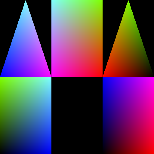
A baked position map of Godot's built-in PrismMesh. RGB is the object-space XYZ of the surface point that lands on each texel.
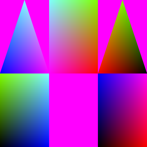
The same bake, dumped again with empty texels written as magenta. Only the exported PNG changes; the map itself still carries coverage in its alpha.
Compare that against the first image. See the dark corner on the right-hand triangle, and the dark bottom of the right-hand rectangle? Those are real surface, texels sitting near the low end of the model's bounds, and in the black version you cannot tell them apart from a hole. Now you can. You get to see the shape of what you did NOT cover, which turns out to be the thing you actually needed to know.
A correct map is unmistakable: smooth gradient islands whose shapes match your UV layout, clean gutters between them. The broken ones are diagnosable at a glance:
- Almost entirely black. No UV0 on the mesh, or you baked a different surface than the one being rendered.
- Flat, uniform colour. Every vertex read as the same position. Usually the index buffer is being walked wrong and you're reading vertex 0 over and over.
- Islands in the wrong place. Right unwrap, wrong Y convention. This baker does no Y flip, so it agrees with anything else that also does none. Mix the two and everything comes out mirrored.
- Speckled holes inside the islands. Resolution too low for the unwrap, so triangles are smaller than a texel and keep missing centers.
And Coverage is that same information as one number, which is what it was for all along. The prism above reads
66.8% at 256 squared, 66.7% at 512, and 66.7% at 1024, which is the useful part: coverage measures your
UNWRAP, not your resolution. It barely moves when you change the texture size, so it makes a good tripwire. A
sudden drop after an art change means somebody's unwrap moved and nobody told you.
Optional: the parts that will bite you
Everything above is the version that explains nicely. Here is the version that survives contact with actual meshes, which is to say, here are four guards that exist because something broke.
// 1. Not every surface is triangles.
if (mesh is ArrayMesh am && am.SurfaceGetPrimitiveType(s) != Mesh.PrimitiveType.Triangles) continue;

// 2. A surface can have no UVs at all.
if (verts.Length == 0 || uvs.Length == 0) continue;

// 3. The index buffer can be EMPTY, on a non-indexed mesh.
int triCount = (idx.Length > 0 ? idx.Length : verts.Length) / 3;
int i0 = idx.Length > 0 ? idx[t * 3]     : t * 3;
int i1 = idx.Length > 0 ? idx[t * 3 + 1] : t * 3 + 1;
int i2 = idx.Length > 0 ? idx[t * 3 + 2] : t * 3 + 2;

// 4. The normals array can be missing or short.
private static Vector3 Nrm(Vector3[] norms, int i) => i < norms.Length ? norms[i] : Vector3.Up;
Number 3 is particularly insidious.
After all that build-up about THE INDEX BUFFER, SurfaceGetArrays will
cheerfully hand you back an empty one, and then every vertex is its own unshared vertex and the triangles are
just consecutive triples. Three lines to support. Not hypothetical either, plenty of generated geometry shows up
like this.
One more thing that isn't a guard: bake from the mesh resource and cache on it. The map depends only on geometry and UVs, so forty copies of the same enemy is one bake, not forty.
private static readonly Dictionary<(ulong mesh, int res), Maps> Cache = new();

public static Maps GetOrBake(Mesh mesh, int resolution)
{
    var key = (mesh.GetInstanceId(), resolution);
    if (Cache.TryGetValue(key, out Maps cached)) return cached;
    ...
}
That sharing is safe no matter where the instances are or how they're rotated, because we baked positions in object space. A world-space bake would be correct for exactly one frame.
And you want that cache, because this is not free. SetPixel is a call across the C#/engine boundary,
that runs for every covered texel twice, and it adds up faster than you would guess. The prism above, on my machine:
  256^2      9 ms
  512^2     35 ms
  1024^2   140 ms
Four times the texels, four times the cost, exactly as you would expect from something that walks texels. Debug build, so release does better. A real enemy mesh with a proper unwrap runs several times that: a messier model I first tested took 26 ms at 256 squared where the prism takes 9.
Optional: The gaps you cannot epsilon away
Back to that half-texel offset, because it has one more consequence and it is the one that will actually show up in your game.
The center is the only point we test. So a triangle covering 40% of a texel that misses its center writes nothing. That's not a bug, every rasterizer works this way.
In a bake that means the outer edge of every UV island comes out ragged at the texel level, and the -1e-4 does
not save you there. That tolerance heals interior edges, where a second triangle was reaching for the same center.
Outside an island there is nothing reaching for anything.
Now, the prism will not show you this, and that is the trap. Its islands sit in a tidy grid with several texels of gutter between them, so it has zero cracks at every resolution I tried. Clean tutorial mesh, clean bake, no problem to see.
Point the same baker at an artist's atlas, where islands are packed tight to win back texture space, and you get this:

30 texels of a hand-unwrapped game mesh's position map, zoomed 18x, gutters in magenta. Two islands packed flush, and a one-texel crack between them that no epsilon can close.
Two islands butted together, each one's silhouette stopping one texel short of the boundary, and a column of nothing straight down the middle. That mesh has 18 of them at 512 squared, 231 texels in total, every single one vertical, and I did not know they existed until I painted the gutters magenta and went looking.
Which is the actual lesson: your test mesh is padded and honest, and it will tell you nothing about this. The bug arrives with the art.
And that bites the moment the texture gets filtered. A bilinear sample near an island's edge blends a real texel with an empty one and hands you a position that is part void. So the real fix, the one every commercial baker ships, is dilation: after baking, flood the empty texels just outside each island with a copy of their nearest real neighbour. A few texels of padding is enough.
Actual use cases
There are multiple use cases for this thing, and it is really, really powerful.
Shaders
Once every texel knows where it is in 3D, any field defined over space can be stamped onto the surface.
Let me repeat. ANY FIELD. And you don't even need to think about UV seams, it just works. It is a texture that knows where it is!
Simplest trick you can pull off with this is a bullet hole. You know where the hit was, so ask every texel whether
it is within r of it, in 3D. Seams stop existing because you never measured anything in UV space.
All you need to do is plug the texture in as a shader uniform and call this:
uniform sampler2D position_map;

vec3 here = texture(position_map, UV).xyz;   // where this texel is, in object space
Which also means you can pair it with the DrawableTexture2D they added in 4.7 and run that test as a blit over
the whole mask:
var sources = new Godot.Collections.Array { _surfaceMaps.Position, _surfaceMaps.Normal };
_mask.Call("blit_rect_multi", rect, sources, ..., _sphereBlit);
uniform sampler2D position_map : hint_blit_source0;
uniform sampler2D normal_map   : hint_blit_source1;
I wrote up that entire path, brush and normal rejection and all, in Painting on a Mesh in Godot 4.
CPU direction
Now, read the position map back on the CPU (GetImage() and then GetPixel(px, py)) and the arrow points the
other way: from a texel to an object-space point, which the node's transform turns into world space. Suddenly the texture has become a queryable record of what happened to
the object in space!
This means you can query the position texture to measure the distance between two parts of the same mesh.
Or if you are using Drawable textures, you can use the position map to paint your texture without having to do a raycast, this can be useful for things that happen in an area, like explosions.
One thing to remember
A rasterizer is a box, three signs, and a blend. But if you keep one sentence out of all of this, keep this one, because every crack, gap, dilation pass and coverage number above is a consequence of it:
The texel center is the only place that exists. A triangle either covers a texel's center or it does not, and everything it covers other than the center is not recorded anywhere. Anything you want to be true about the half-covered texels at the edges, you have to go and add yourself, afterwards.
One last note:
Source code for this is here Painting on a Mesh in Godot 4, at the bottom.